The following example problem illustrates the use of this procedure.
Example Problem 4-1
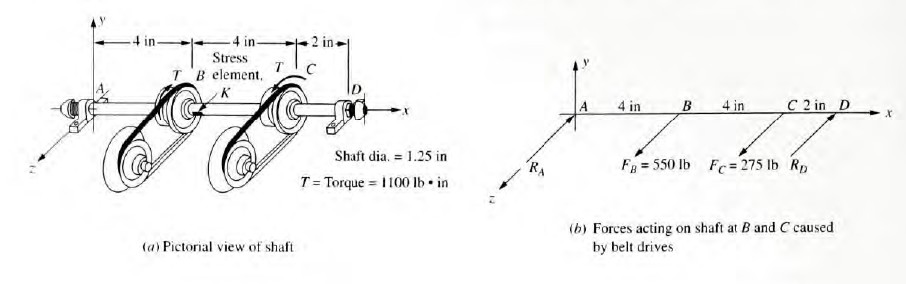
The shaft shown in figure 4-7 is supported by two bearings and carries two V-belt sheaves. The tensions in the belts exert horizontal forces on the shaft, tending to bend it in the x-z plane. Sheave B exerts a clockwise torque on the shaft when viewed toward the origin of the coordinate system along the x-axis. Sheave C exerts an equal but opposite torque on the shaft. For the loading condition shown, determine the principle stresses and the maximum shear stress on element K on the front surface of the shaft (on the positive z-side) just to the right of sheave B. Follow the general procedure for analyzing combined stresses given in this section.
Solution
Objective: Compute the principal stresses and the maximum shear stresses on element K.
Given: Shaft and loading pattern shown in Figure 4-7.
Analysis: Use the general procedure for analyzing combined stresses.
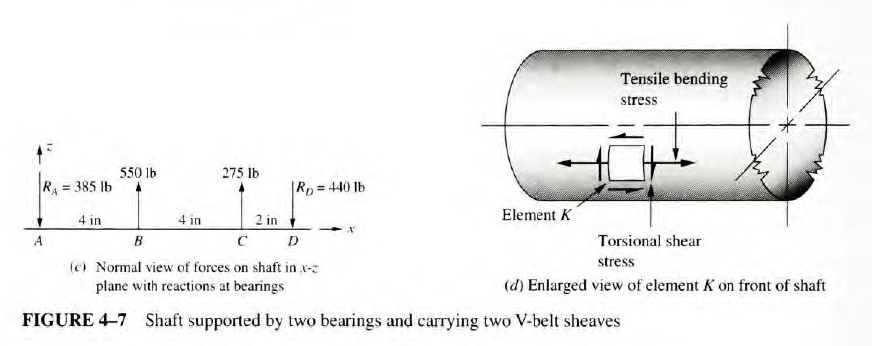
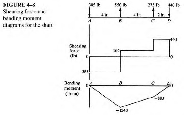
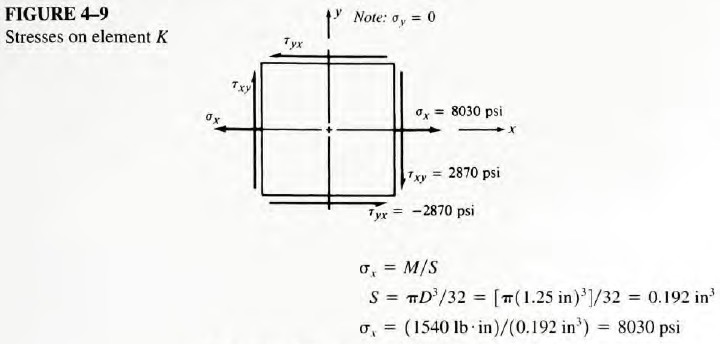
Results: Element K is subjected to bending that produces a tensile stress acting in the x-direction. Also, there is a torsional shear stress acting at K. Figure 4-8 shows the shearing force and bending moment diagrams for the shaft and indicates that the bending moment at K is 1540 lb-in. The bending stress is therefore
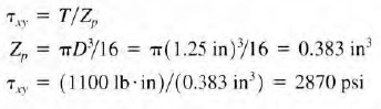
The torsional shear stress acts on element K in a way that causes a downward shear stress on the right side of the element and an upward shear stress on the left side. This action results in a tendency to rotate the element in a clockwise direction, which is the positive direction for shear stresses according to the standard convention. Also, the notation for shear stresses uses double subscripts. For example, τxy indicates the shear stress acting on the face of an element that is perpendicular to the x-axis and parallel to the y-axis. Thus, for element K,
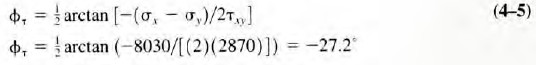
The principal stresses can be shown on a stress element as illustrated in Figure 4-10. Note that the element is shown in relation to the original element to emphasize the direction of the principal stresses relation to the original x-axis. The positive sign for ϕσ indicates that the principal stresses element is rotated clockwise from its original position.
Now, the maximum shear stress element can be defined, using Equations (4-4) through (4-6):
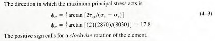
The values of the normal stress, σxy, and the shear stress, τxy, are shown on the stress element K in Figure 4-9. Note that the stress in the y-direction is zero for this loading. Also, the value of the shear stress, τyx, must be equal to τxy, and it must act as shown in order for the element to be in equilibrium.
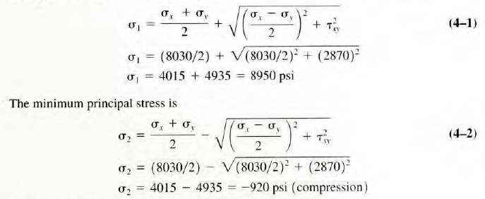
We can now compute the principal stresses on the element, using Equations (4-1) through (4-3). The maximum principal stress is
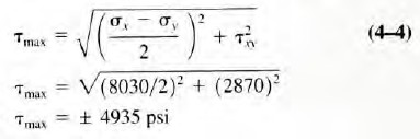
The two pairs of shear stresses, +τmax and - τmax, are equal in magnitude but opposite in direction.
The orientation of the element on which the maximum shear stress acts is found from Equation (4-5):
The negative sign calls for a counterclockwise rotation of the element.
There are equal normal stresses acting on the faces of this stress element, which have the value of
Comments: Figure 4-11 shows the stress element on which the maximum shear stress acts in relation to the original stress element. Note that the angle between this element and the principal stress element is 45°.

Examine the results of Example Problem 4-1. The maximum principal stress, σ1 = 8950 psi, is 11 percent greater than the value of σx = 8030 psi computed for the bending stress in the shaft acting in the x-direction. The maximum shear stress, τmax = 4935 psi, is 72 percent greater than the computed applied torsional shear stress of τxy = 2870 psi. You will see in Chapter 5 that either the maximum normal stress or the maximum shear stress is often required for accurate failure prediction and for safe design decisions. The angles of the final stress elements also predict the alignment of the most damaging stresses that can be an aid in experimental analysis and the analysis of actual failed components.
Another concept, called the von Mises stress, is used in the distortion energy theory of failure described in Chapter 5. The von Mises stress is a unique combination of the maximum principal stress, σ1, and the minimum principal stress, σ2, which can be compared directly with the yield strength of the material to predict failure by yielding.
The process of computing the principal stresses and the maximum shear stress shown in Example Problem 4-1 may seem somewhat abstract. These same results can be obtained using a method called Mohr's circle, which is discussed next. This method uses a combination of a graphical aid and simple calculations. With practice, the use of Mohr's circle should provide you with a more intuitive feel for the variations in stress that exist at a point in relation to the angle of orientation of the stress element. In addition, it provides a streamlined approach to determining the stress condition on any plane of interest.
SAMPLE PROBLEM NO. 1