SAMPLE PROBLEM NO. 2

We will now illustrate the construction of Mohr's circle by using the same data as in Example Problem 4-1, in which the principal stresses and the maximum shear stress were computed directly from the equations.
Example Problem 4-2
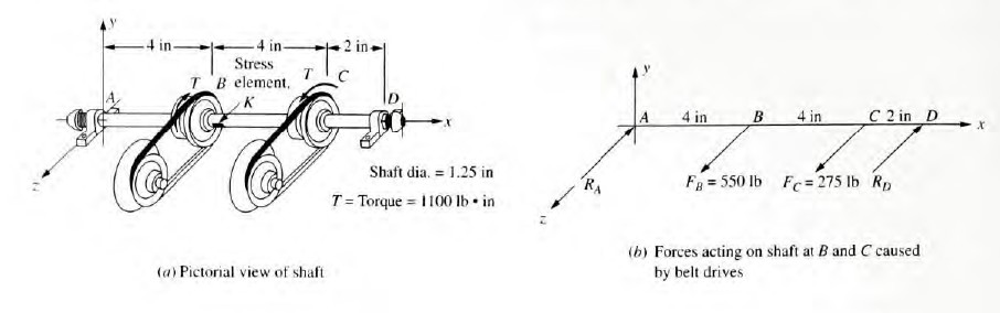
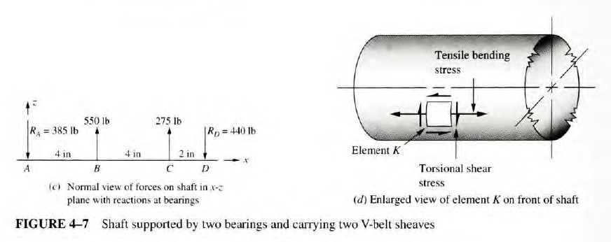
The shaft shown in Figure 4-7 is supported by two bearings and carries two V-belt sheaves. The tensions in the belts exert horizontal forces on the shaft, tending to bend it in the x-z plane. Sheave B exerts a clockwise torque on the shaft when viewed toward the origin of the coordinate system along the x-axis. Sheave C exerts an equal but opposite torque on the shaft. For the loading condition shown, determine the principal stresses and the maximum shear stress on element K on the front surface of the shaft (on the positive z-side) just to the right of sheave B. Use the procedure for constructing Mohr's circle in this section.
Solution:
Objective: Determine the principal stresses and the maximum shear stresses on element K.
Given: Shaft and loading pattern shown in Figure 4-7.
Analysis: Use the Procedure for Constructing Mohr's Circle. Some intermediate results will be taken from the solution to Example Problem 4-1 and from Figures 4-7, 4-8, and 4-9.
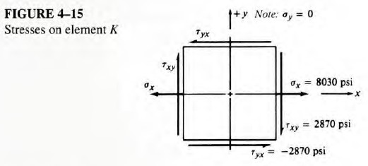
Results: Steps I and 2. The stress analysis for the given loading was completed in Example Problem 4-1. Figure 4-15 is identical to Figure 4-9 and represents the results of Step 2 of
the Mohr's circle procedure.
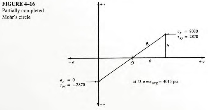
Steps 3-6. Figure 4-16 shows the results. The first point plotted was
The second point was plotted at
Then a line was drawn between them, crossing the σ-axis at O. The value of the stress at O is
Step 7. We compute the values for a, b. and R from
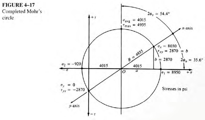
Step 8. Figure 4-17 shows the completed Mohr's circle. The circle has its center
at O and the radius R. Note that the circle passes through the two points originally plotted. It must do so because the circle represents all possible states of stress on the element K.
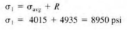
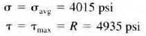
Step 9. The maximum principal stress is at the right side of the circle.
Step 10. The minimum principal stress is at the left side of the circle.
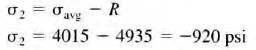
Step 11. At the top of the circle,
The value of the normal stress on the element that carries the maximum shear stress is the same as the coordinate of O, the center of the circle.
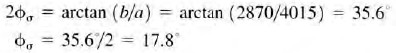
Step 12. Compute the angle 2ϕσ and then ϕσ. Use the circle as a guide.
Note that ϕσ must be measured clockwise from the original x-axis to the direction of the line of action of σ1 for this set of data. The principal stress element will be rotated in the same direction as part of step 14..
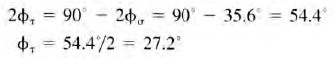
Step 13. Compute the angle 2ϕτ, and then ϕτ. From the circle we see that
Note that the stress element on which the maximum shear stress acts must be rotated counterclockwise from the orientation of the original element for this set of data.
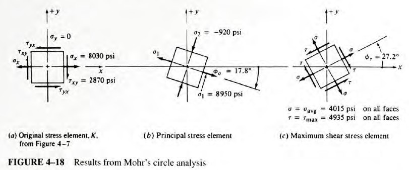
Step 14. Figure 4-18 shows the required stress elements. They are identical to those shown in Figure 4-11.